SRS Control Panel is the integrated radio management interface of DCS Airspace. It allows ATC, AWACS and GCI controllers to manage radios, frequencies, channels and transmission parameters directly from DCS Airspace while synchronizing the configuration with DCS Simple Radio Standalone (SRS) in real time.
The SRS Control Panel connects the tactical airspace picture provided by DCS Airspace with the radio communication environment provided by SRS. This allows controllers to work with mission-specific communication plans, radio frequencies and transmission states without having to configure the same information separately in multiple interfaces.
Requirements:
- SRS Version: 2.4.0.0 or higher
- Combined Ops Link Version: 0.1.3.2 or higher
1. SRS Control Panel Overview and Connection Status
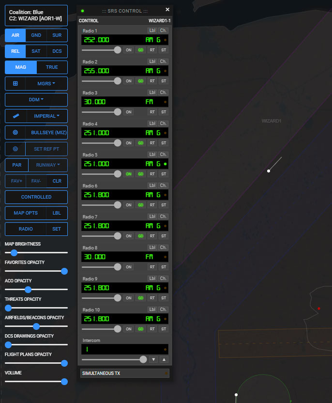
The top bar of the SRS Control Panel displays the current synchronization status and the geographic or unit context used for radio communication.
-
Connection Status Indicator: A status LED located at the top-left of the panel indicates the connection status to Combined Ops Link. Combined Ops Link runs locally on the controller's computer and acts as the communication bridge between the local SRS Client and DCS Airspace. It communicates with the configured SRS Server and provides the data required for real-time radio and frequency synchronization.
-
Control / Location Display: Displays the current geographic or operational reference, such as an active airbase or selected air unit. Position and altitude information are continuously updated to support realistic radio propagation within SRS and DCS World.
2. Radio Controls and SRS Channels
The SRS Control Panel provides dedicated controls for Radio 1 through Radio 10 and an Intercom channel. Controllers can configure frequencies manually or load communication presets from the Comm Plan associated with the current DCS Airspace operation.
Channel Features
-
Frequency Input: Frequencies can be entered manually in the display field or loaded from the Comm Plan, when available through DCS AOC Tools, using the channel selector menu (Ch. button). Manual frequency entries automatically validate the input length and modulation type (AM/FM).
-
Display Label Toggle (Lbl): The label control cycles the information displayed for a communication channel between the Callsign, ID, Type, or a blank field. When available, these labels are derived from the operational Comm Plan.
-
Channel Selector (Ch.): Opens a filtered list of available preset channels from the active Comm Plan, organized according to modulation type.
-
Radio Activation (ON): Sets the selected radio as the primary transmission radio. Only one radio can be designated as the primary transmission channel at a time.
-
Volume Slider: Controls the output volume of each individual radio receiver.
3. Advanced Radio Transmission Functions
Each standard radio provides additional controls for managing advanced SRS transmission and reception functions.
-
Guard Reception (GD): Enables or disables monitoring of the designated Guard frequency for the selected radio when supported by the configured channel.
-
Radio Retransmit (RT): Enables or disables radio retransmission on the selected channel, allowing incoming transmissions to be automatically relayed to another configured frequency.
-
Simultaneous Transmission (ST): Enables secondary radio channels to transmit simultaneously with the primary radio.
-
Global Simultaneous TX Mode: Located at the bottom of the panel, the global Simultaneous TX control enables the use of ST on multiple radio channels at the same time. Disabling global simultaneous transmission automatically disengages all active secondary transmission channels.
4. Intercom System
-
Channel Selection: Use the step controls (▲ / ▼) or enter a channel number directly to switch between the available internal intercom channels from 1 to 30.
-
Volume Control: Provides an independent volume adjustment for the intercom, separate from the tactical radio channels.
5. Radio Location Assignment
The SRS Control Panel can associate radio transmissions with a specific geographic position or DCS World asset. This allows the radio environment to reflect the controller's operational position within the mission.
-
Select an Airbase or an allowed Live Unit on the DCS Airspace tactical map.
-
Activate the SET location button in the left-side menu.
-
The selected airbase or unit name will appear in the panel header, while its latitude, longitude and elevation are synchronized automatically.
6. SRS and DCS Airspace Connection Guide
To enable complete synchronization between DCS Airspace, Combined Ops Link and SRS, follow these steps before starting controller operations:
-
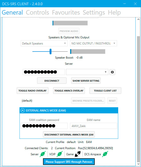
Connect the SRS Client: Launch the local SRS Client, connect to the required SRS Server as usual, and enable External AWACS Mode (EAM).
-
Launch Combined Ops Link: Start the Combined Ops Link application on the controller's local computer.
-
First-time setup: If this is the first time Combined Ops Link is being used, configure its connection to the required SRS Server manually. Subsequent launches will automatically use the saved server profile.
-
-
Open DCS Airspace: Open or refresh the DCS Airspace browser application. The SRS Control Panel status indicator will become active once the synchronization between DCS Airspace, Combined Ops Link and SRS has been established.
Note: Custom panel configurations, volume levels, selected frequencies, and active radio functions are automatically saved and restored across sessions.