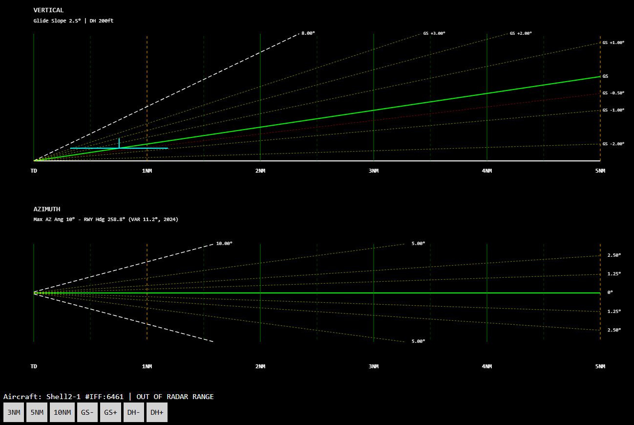
The Precision Approach Radar (PAR) in DCS Airspace is a dedicated radar approach system for Air Traffic Controllers (ATC) in DCS World. It provides real-time azimuth and elevation guidance to help controllers monitor and guide aircraft during the final phase of an instrument approach.
The integrated DCS Airspace PAR system reproduces the essential controller displays used for a precision radar approach, allowing the controller to monitor an aircraft's lateral and vertical position relative to the selected runway approach path and provide appropriate corrections to the pilot.
PAR System Overview
The PAR system displays the aircraft's position relative to the ideal approach path on two dedicated radar displays:
- Elevation Display: Shows the aircraft's vertical deviation from the Glide Slope and its distance from the runway threshold.
- Azimuth Display: Shows the aircraft's lateral deviation from the Localizer (runway centerline) and its distance from the runway threshold.
Both displays feature a static reference grid representing the ideal glide slope and runway centerline. This allows the controller to assess deviations in real time and provide immediate heading and altitude corrections to the aircraft.
Initial PAR Configuration
Before using the DCS Airspace PAR, the controller must configure the active airbase and runway for the approach.
- Airbase Selection: In the map control panel, usually located on the left side of the interface, locate the button group labeled PAR. Click the PAR button to enable PAR functionality and select the required airbase.
- Runway Selection: Once the airbase has been selected, the adjacent RUNWAY button becomes active. Click it to open the dropdown menu and select the runway to be used for the PAR approach. Only runways configured with PAR capability are available for selection.
Once the airbase and runway have been configured, the PAR system is ready to receive aircraft data and display the selected approach geometry.
Opening the PAR Window
To display the PAR presentation for a specific aircraft, first select the aircraft on the tactical map and then open the dedicated PAR display.
Select the Aircraft: On the DCS Airspace map, select the aircraft of interest by clicking on its track.
Open the PAR Window: In the right-hand tool panel, locate the PAR button and click it to open the dedicated PAR display for the selected aircraft.
The PAR window then displays the aircraft's real-time position relative to the selected glide slope and runway centerline.
Interpreting the PAR Display
The DCS Airspace PAR display provides the controller with the information required to monitor the aircraft's approach path and identify lateral, vertical, and range deviations.
Displayed Data
- Aircraft Plot: A bright dot (plot) represents the aircraft's current position.
- Trail: A series of smaller dots behind the main plot represents the aircraft's recent trajectory and provides a visual indication of its approach trend.
- Reference Grid: Angular and vertical reference lines form a grid that helps the controller quantify aircraft deviations from the desired approach path.
- Angular Lines: These lines have different meanings depending on the display:
- Elevation Display: Represents the ideal glide slope and vertical deviations from it.
- Azimuth Display: Represents the runway centerline and lateral deviations from it.
- Vertical Lines: Indicate the aircraft's range and distance from the runway threshold.
- Aircraft Information: Key aircraft information, including callsign, heading, airspeed, and deviation in feet, is displayed for the controller.
PAR Controls and Adjustments
The PAR window provides controls that allow the controller to adjust the display scale and approach parameters according to the aircraft's position and the requirements of the approach.
- Distance Scales: Scales such as 3 NM, 5 NM, and 10 NM allow the controller to change the horizontal range displayed by the PAR. The selected scale also affects the maximum vertical scale shown on the elevation display. The appropriate scale can therefore be selected according to the aircraft's distance from the runway threshold.
- Glide Slope Adjustment: The GS- and GS+ controls decrease or increase the selected ideal glide slope angle in 0.5-degree increments. The glide slope can be adjusted between 0.0 and 10.0 degrees.
- Decision Height Adjustment: The DH- and DH+ controls decrease or increase the Decision Height in 50-foot increments. The Decision Height can be configured between 50 and 500 feet.
Operational Use of PAR
DCS Airspace PAR is designed to support realistic ATC precision approach operations in DCS World. During an approach, controllers can use the azimuth and elevation displays, aircraft trend information, range scales, and approach parameters to maintain awareness of the aircraft's position relative to the desired approach path.
The PAR display is intended to complement controller-pilot communication. The controller remains responsible for interpreting the displayed information and providing appropriate heading and altitude instructions through the mission's established communication procedures.
Operational Tips
Constant Communication: Maintain clear and concise communication with the pilot, providing heading and altitude instructions based on the aircraft's displayed deviations.
Anticipation: Anticipate necessary corrections, particularly at close distances to the runway threshold, to avoid excessive deviations from the approach path.
Trail Monitoring: Use the aircraft plot trail to assess approach stability and evaluate the effectiveness of the pilot's previous corrections.
Decision Height: Closely monitor the aircraft's altitude in relation to the configured Decision Height during the final phase of the approach.